I've learned A LOT about solar panels and batteries. Too much to write here. But basically, my goal has been to put together a power system as cheaply as possible without sacrificing too much in efficiency.
One large expense for most solar setups is the solar charge controller. Usually you want to use an MPPT charge controller for max efficiency, but these can be quite expensive. Also, for this particular application, the size of the charge controller becomes important, as it could easily be the largest single electronic component, and I really don't have a lot of room for it. Where an MPPT charge controller is really essential is when the solar panel voltage is much higher than the battery voltage. So, at the recommendation of a friend, I am trying to get rid of the charge controller by bringing the battery voltage up to the level of the solar panel voltage. It just so happens that a five-cell LiFePo4 battery's voltage is just about the same as the Renogy solar panel's maximum power voltage.
The behavior of a solar panel connected directly to a battery is similar to your typical CC-CV lithium battery charger: a lot of current until the battery gets close to fully charged, and then the voltage rises while the current decreases (the solar panel will put out less current as the voltage rises). TO put numbers to this, the Renogy solar panel's max power voltage is 17.7 volts (depending on temperature) and the 5-cell LiFePo4 battery's nomial voltage is 16 volts and its fully-charged voltage is 18 volts. So my first power system consisted of nothing more than the solar panels directly connected to the batteries. But there were two problems. The first is that, while the solar panel current output drops off drastically as voltage increases, it doesn't drop to zero until the battery voltage is about 21 volts. That's 4.2 volts per cell, a little too high for these cells. And that's assuming that all the cells are perfectly balanced, which brings us to the second problem...
The second problem is that with multiple cells in series, there will be one cell that reaches capacity before the others, so its voltage will skyrocket before the other cells reach capacity, damaging that cell. So instead of all the cells reaching 4.2 volts, you might have four of them reaching 4.0 volts and the fifth reaching 5.0 volts, WAY too high for these cells. This problem can be minimized by starting off with the cells being "balanced," but they'll never be perfectly balanced. And even if they start off perfectly balanced, they won't be that way after several charge-discharge cycles.
So it becomes necessary to add a battery balancing circuit. There's a lot of these circuits out there, and they usually perform other useful functions such as high voltage cutoff, low voltage cutoff, high and low temperature cutoff, high current cutoff, etc. Unfortunately, it's difficult to find such circuits for 5-cell batteries. And they usually expect a certain input voltage. In the case of the circuit that I found, it expects an 18-volt input voltage, not the 21 volts that the solar panel can potentially provide. So I added a linear voltage regulator with the output voltage set to 18 volts.
The one thing I'm still missing is a blocking diode to prevent the loss of energy from the battery forcing current backward through the solar panels at night.
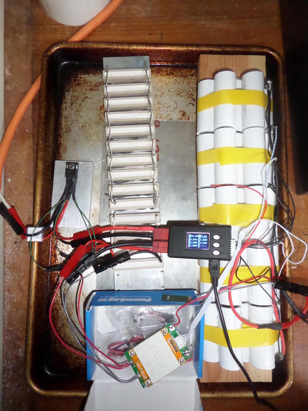
Clockwise from left: voltage regulator, resistor bank (to be replaced by motor), batteries, balancing board. Data logger is in the middle.


 RSS Feed