Check out the tracking page!
|
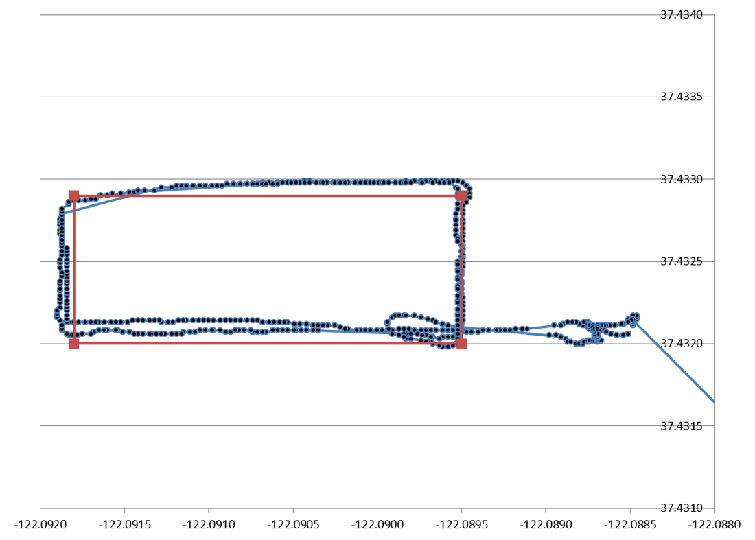
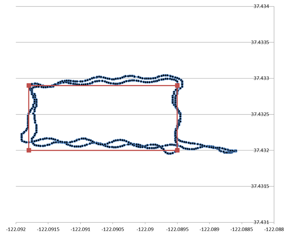
Today I put the boat back in the water to test the autopilot again. After making a few autopilot parameter changes and replacing the rudder actuator with one made by Troy and Matt (thanks guys!!!!), the boat follows the course much better. I could probably make the autopilot track the course more tightly, but on the open ocean, it's not really necessary. The key thing is that the boat is going in smooth, straight lines.
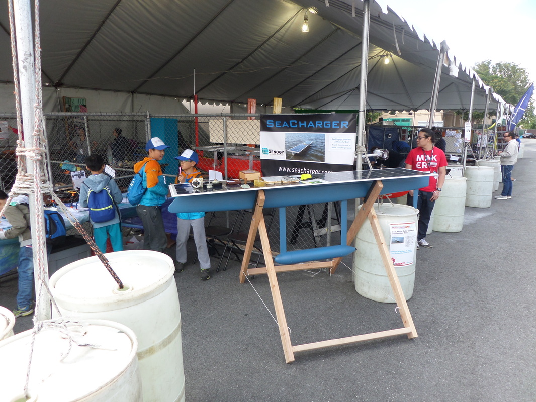
SeaCharger was at MakerFaire in San Mateo this past weekend. It was an amazing experience. This picture was taken on a Friday, which was relatively quiet. But on Saturday there was a constant stream of people. Thank you to all of you who came by for your enthusiasm and encouragement! I committed to about 500 people that I would launch this thing on Memorial Day, so I guess I had better do it.
Today was a big milestone! I ran the boat autonomously for the first time today in Shoreline Lake in Mountain View. The picture above shows the boat's track as it did two laps around the lake (the red line is the intended track, the blue/black lines are the actual path). Sure, it looked a bit like a drunken sailor, but it DID work. Just gotta tune some gains.
The cool thing about a project like this is that it encompasses so many different disciplines. I'm mainly a mechanical guy, but I'm getting to learn a lot about autopilots and navigation and Arduino.
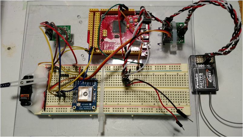
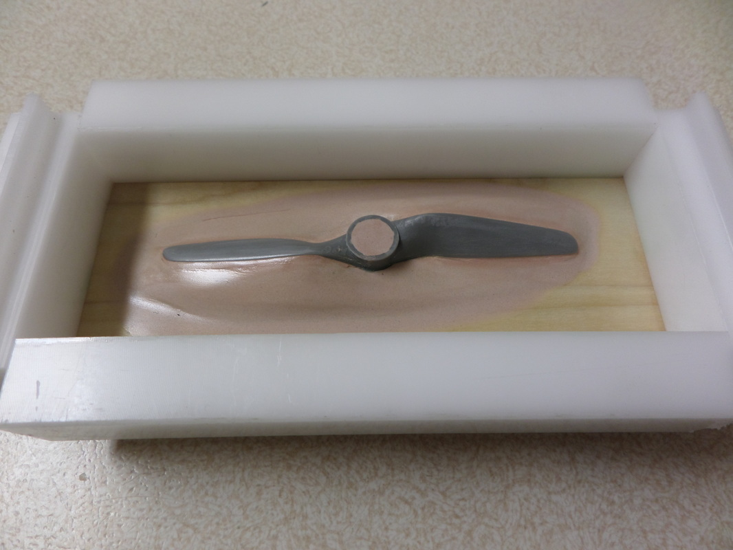
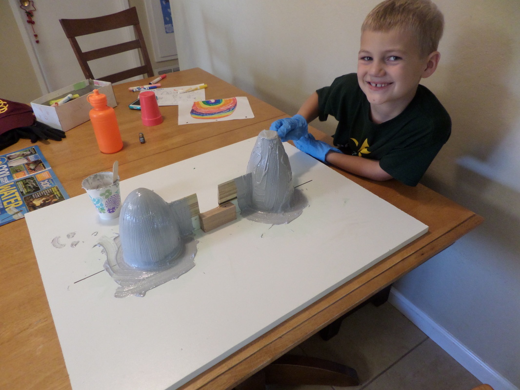
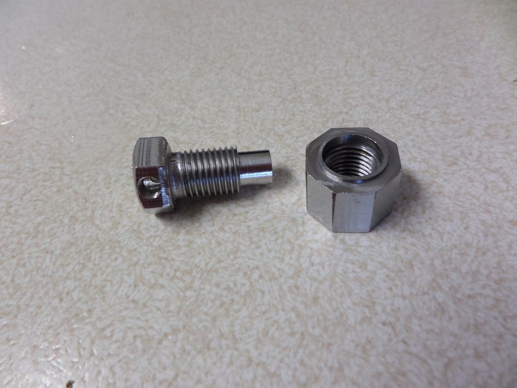
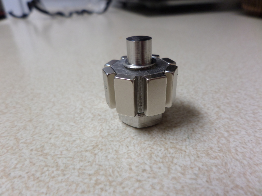
Here you see the beginnings of Seacharger's autopilot. Clockwise from the upper left: tilt-compensated compass (Devantech CMPS-11), Seeeduino Mega (basically an Arduino Mega in a slightly smaller form factor), servo mux board from Pololu, R/C receiver, Adafruit GPS, and a servo. Special thanks to JT for putting together all these components and getting them to talk to each other! After reading about Arduino code and making a mockup of the autopilot in Excel, I managed to get a pretty decent autopilot working. What I mean by this is that I could program in some waypoints and then take this setup to a local park and have it guide me to the waypoints by moving the servo arm in the direction it wanted me to walk. There were a lot of bugs in the code, mainly having to do with passing from 359 degrees heading to 0 degrees heading or from 180 degrees to -180 degrees. But I got all those worked out and it's all good now. This kind of work is really fun because you can make progress so quickly. Those software guys have it easy! It's funny, in many things I'm more than happy with "good enough," but in other things I'm a perfectionist. Well now I'm at a stage in the project where I start second-guessing some of my previous work and then redoing a lot of it. One thing I've decided to "fix" is the propeller. I've been using off-the-shelf model airplane propellers which are made out of fiber-reinforced nylon. It turns out that that doesn't do too well in water. I took one brand new propeller and dipped it in a cup of freshwater overnight and felt it in the morning. The portion of the propeller that had been submerged was now much less stiff. That explains why my propellers have been looking very bent after a few hours of running in water. So what do do? Make a carbon fiber/epoxy propeller, of course! This actually is fairly easy if you're copying an existing propeller, like I am. In the picture above you can see an off-the-shelf propeller that I've placed on a bed of Bondo to form the plug. After sanding and waxing, I poured pure epoxy onto the plug. I've never done it this way before; normally you'd use fiberglass to make the mold. But using epoxy alone is nice because it makes the mold transparent, which then makes actually using the mold a lot easier, since you can see what the fibers and epoxy are doing inside the mold. I would include a picture of the finished propeller but you really don't need to see it. It looks just like the propeller above except that it's black. Simple as that. Other things I decided to redo were the nose cone and tail cone on the thruster. This was probably unnecessary, and ended up being a lot of work. But my previous nose and tail cones were pretty rough and they didn't interface with the struts on the thruster very nicely. So I made the plugs you see in the picture above, which then got molds pulled off of them, which then got fiberglass parts pulled off of them. Nose cone is on the left, tail cone on the right, and you can see that they each have a portion of dummy strut jutting out. So the parts that got made from these molds have perfectly-shaped openings for the struts. That's my son helping to brush on a layer of gel coat. The other thing I really wanted to redo was the magnetic coupling. It was simply too large, especially the portion that was wet. This meant that I would be losing precious watts just from spinning the coupling itself. So I made a smaller one. I worked hard to design it such that it would be easy to fabricate with my limited resources. It's made out of the 316 stainless steel screw that you see on the left, with a hole drilled down the center for the propeller shaft and a cross-hole for a set screw. Then the other piece shown in the pictures started out as a mild steel tube, which I tapped to match the screw's thread and milled flats on for the magnets to stick to. The mild steel acts as a "back-iron" to amplify and guide the magnetic field and has the added benefit of being easy to machine (compared to stainless steel). I threaded this piece onto the screw, added the magnets, and then potted the whole thing in epoxy (potting not shown). The coupling rides on a ceramic bearing. This is the half of the coupling that will go in the water, and will probably take less than half the power to spin in the water than my old coupling.
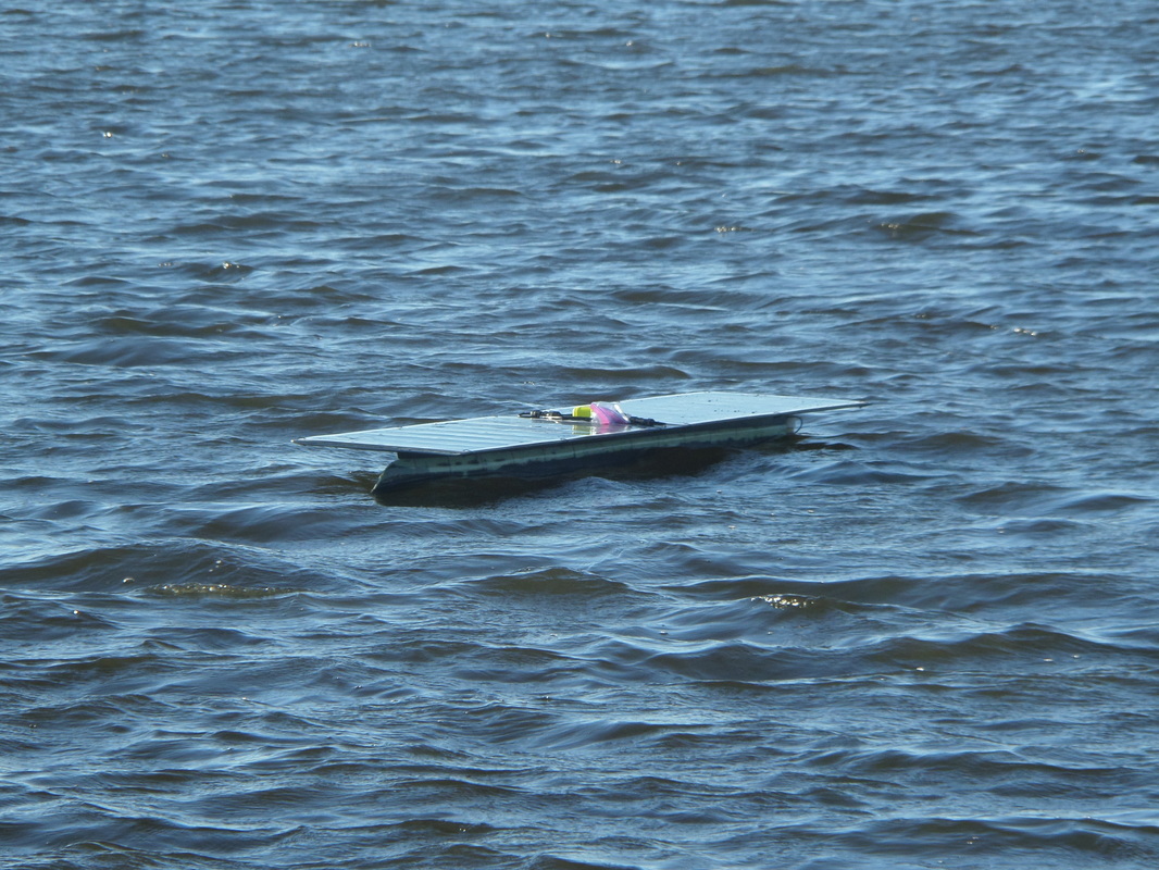
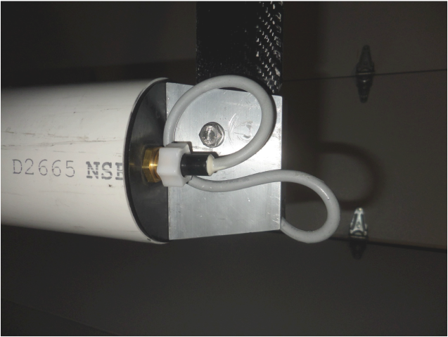
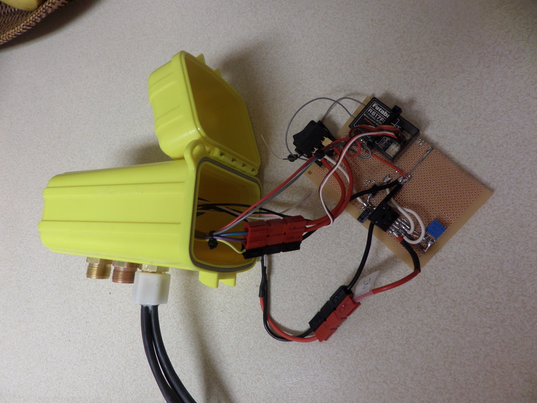
The After several months in "drydock," the boat went back in the water last weekend. There's a lot of stuff on the boat that wasn't on there before: new carbon fiber struts to connect the hull to the thruster, a truly waterproof rudder actuator, new waterproof electrical connectors, a drybox for the electronics, real batteries, and most importantly, solar panels (thanks Renogy!). The boat now weighs just over 50 pounds and will most likely not gain any more weight. The testing this last weekend showed that its speed is essentially the same as the last time it was in the water several months ago (about 3 mph at 20 watts). Although it weighs more now, the struts are also more streamlined, so apparently those two factors balanced each other out. I'm still missing a fairing on the rear end of the boat, which ought to clean it up a lot and add a bit of speed. And I need to get a stiffer propeller, as the current plastic one bends too much under load. That might help a little with the speed too. Here are some pictures of various components. The first one is the front of the thruster pod. The black thing sticking out the top of the photo is the carbon fiber strut. There's an aluminum bracket connecting the thruster pod to the strut. The gold-colored thing is the brass bulkhead connector made from a compression fitting, with a few additional features machined in. The cable is molded in as part of the strut. The yellow box in the picture below is my electronics enclosure. It's just an off-the-shelf enclosure with holes drilled in the side for a few bulkhead connectors. Then you see my beautiful attempt at a circuit board to the right. It's got a voltage regulator to cap the solar panel voltage, the R/C receiver, and a power switch. Eventually all this will be organized better and an autopilot and satellite modem will be added.
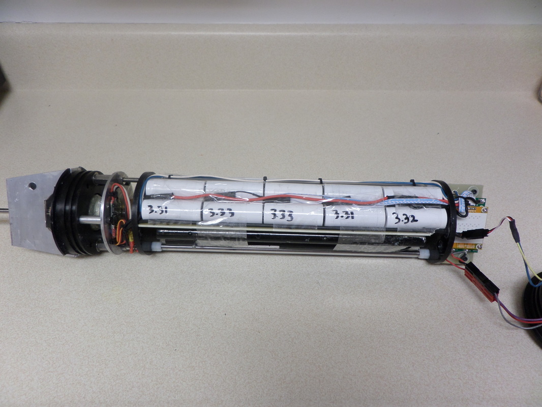
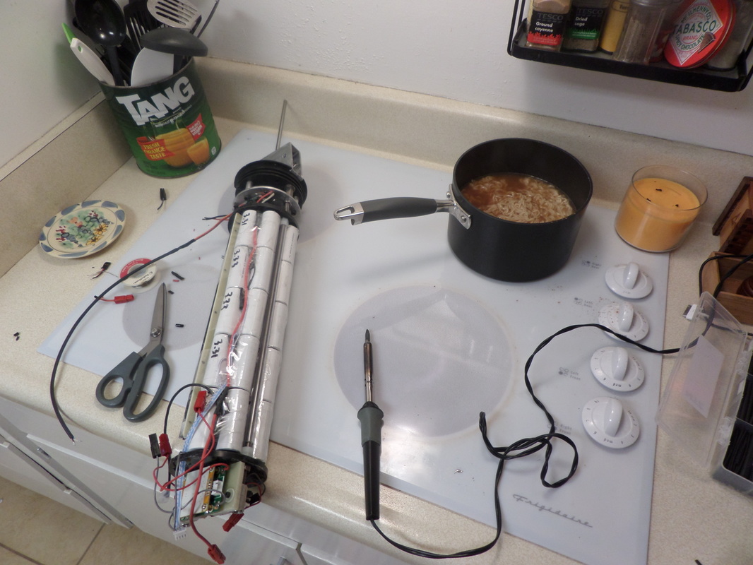
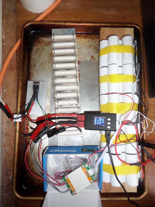
With the power system more or less figured out, it was time to move all these components from the test bench to the actual boat. It sorta looks like a bomb, but don't worry, it's not. In the picture below, going from left to right, you have: - aluminum bracket on the rear of the thruster pod for mounting to the rear strut (the vertical member that connects the thruster pod to the boat hull). The aluminum is electrically isolated from everything else to prevent corrosion - black delrin thruster pod end cap (no change from the old thruster) - aluminum thruster motor mounting plate, motor, belt drive, electronic speed control (no change from old thruster) - battery pack... those white cylinders are 25 cells, 5 in parallel X 5 in series. I will eventually have a total of fifty. Below the battery pack is a bunch of steel bars for ballast. It turns out the thruster pod is going to need a lot of dead weight to make it act as a keel. - at the right, the battery charge controller and DC/DC switching regulator. The regulator is to bring the 16 volts from the battery down to 5-7 volts for the motor. The idea is that it's more efficient to use a dedicated regulator (which is >90% efficient) to bring the voltage down BEFORE the electronic speed control, so that the speed control can operate near 100% throttle. The voltage needs to be brought down to get the motor to spin slow enough to use a large, slow-spinning propeller. The study of direct drive vs. gear drive vs. belt drive, high voltage vs. low voltage, and a myriad of other factors, has been both frustrating and enlightening. Who knows if I have settled up the "right" configuration. I think I'm close, though. - hanging off the right end of the picture is the other thruster tube end cap with a homemade, waterproof bulkhead connector Surrounding all this will be the thruster tube itself, which is just a piece of PVC pipe. Now, if anyone out there is wondering why it takes so long to do a project like this, let me remind you that there are other, far more important things competing for my time. I present as evidence this photograph of me soldering on the stovetop while cooking Ramen for my kids. I'm not sure which is more dangerous: having a burning hot pot right next to a burning hot soldering iron surrounded by power cords and huge batteries, or eating Ramen. Probably the Ramen. Usually the kids eat better, trust me.
I've learned A LOT about solar panels and batteries. Too much to write here. But basically, my goal has been to put together a power system as cheaply as possible without sacrificing too much in efficiency.
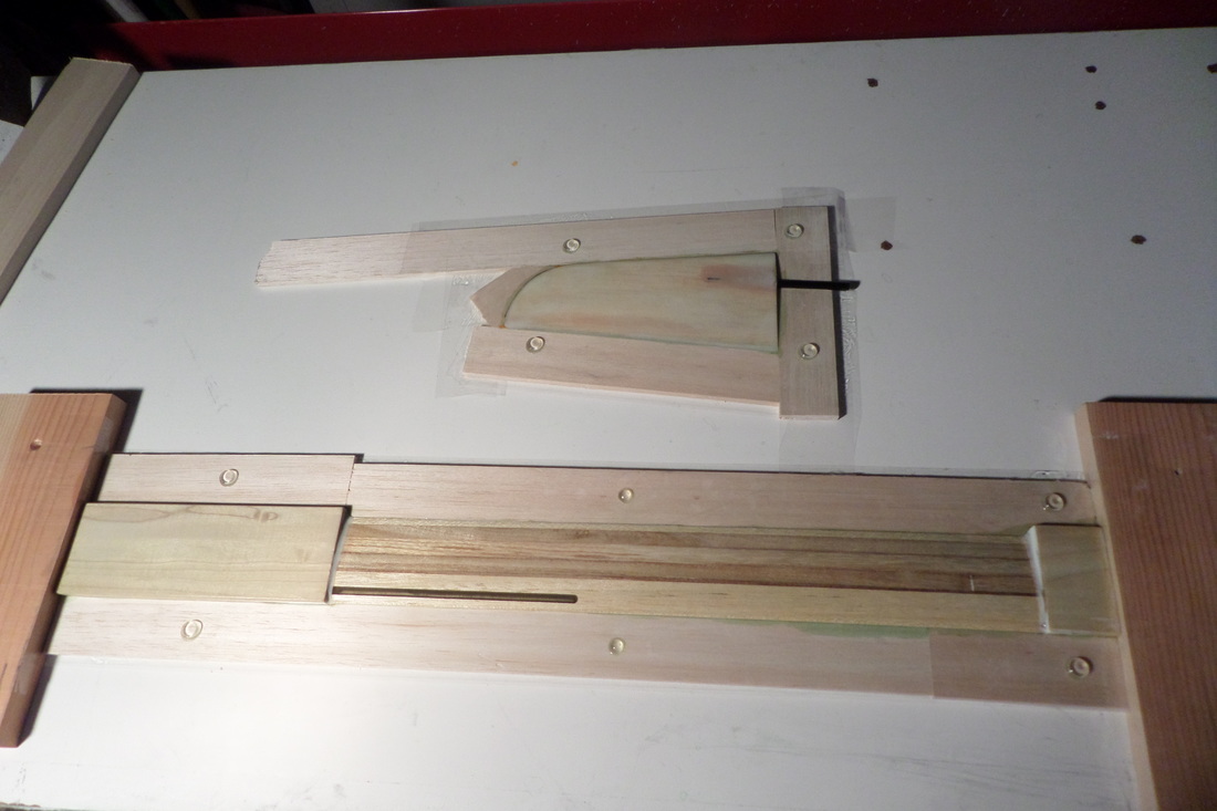
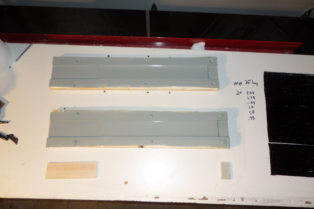
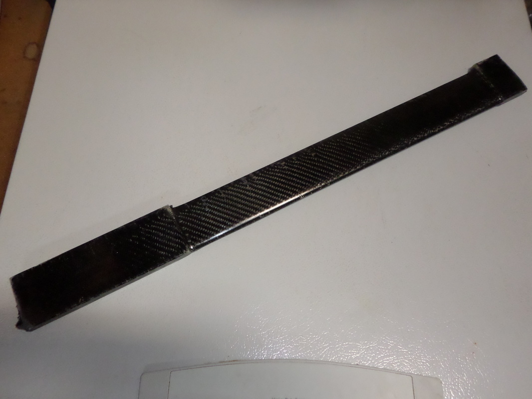
One large expense for most solar setups is the solar charge controller. Usually you want to use an MPPT charge controller for max efficiency, but these can be quite expensive. Also, for this particular application, the size of the charge controller becomes important, as it could easily be the largest single electronic component, and I really don't have a lot of room for it. Where an MPPT charge controller is really essential is when the solar panel voltage is much higher than the battery voltage. So, at the recommendation of a friend, I am trying to get rid of the charge controller by bringing the battery voltage up to the level of the solar panel voltage. It just so happens that a five-cell LiFePo4 battery's voltage is just about the same as the Renogy solar panel's maximum power voltage. The behavior of a solar panel connected directly to a battery is similar to your typical CC-CV lithium battery charger: a lot of current until the battery gets close to fully charged, and then the voltage rises while the current decreases (the solar panel will put out less current as the voltage rises). TO put numbers to this, the Renogy solar panel's max power voltage is 17.7 volts (depending on temperature) and the 5-cell LiFePo4 battery's nomial voltage is 16 volts and its fully-charged voltage is 18 volts. So my first power system consisted of nothing more than the solar panels directly connected to the batteries. But there were two problems. The first is that, while the solar panel current output drops off drastically as voltage increases, it doesn't drop to zero until the battery voltage is about 21 volts. That's 4.2 volts per cell, a little too high for these cells. And that's assuming that all the cells are perfectly balanced, which brings us to the second problem... The second problem is that with multiple cells in series, there will be one cell that reaches capacity before the others, so its voltage will skyrocket before the other cells reach capacity, damaging that cell. So instead of all the cells reaching 4.2 volts, you might have four of them reaching 4.0 volts and the fifth reaching 5.0 volts, WAY too high for these cells. This problem can be minimized by starting off with the cells being "balanced," but they'll never be perfectly balanced. And even if they start off perfectly balanced, they won't be that way after several charge-discharge cycles. So it becomes necessary to add a battery balancing circuit. There's a lot of these circuits out there, and they usually perform other useful functions such as high voltage cutoff, low voltage cutoff, high and low temperature cutoff, high current cutoff, etc. Unfortunately, it's difficult to find such circuits for 5-cell batteries. And they usually expect a certain input voltage. In the case of the circuit that I found, it expects an 18-volt input voltage, not the 21 volts that the solar panel can potentially provide. So I added a linear voltage regulator with the output voltage set to 18 volts. The one thing I'm still missing is a blocking diode to prevent the loss of energy from the battery forcing current backward through the solar panels at night. Up until now, the strut that connects the thruster pod to the hull has been a bit clunky. It was a rectangular piece of G10 (a type of high-quality fiberglass laminate) with a floppy fiberglass fairing loosely wrapped around it. So I'm replacing that with two thin, streamlined carbon fiber struts in tandem. A previous post showed how I made the plug for the struts and the rudder. Now I'm going to make molds off those plugs. First I took the plugs and surrounded them with material to put the mold parting line at the right place. Notice also the little clear plastic stick-on drawer bumpers. They will make perfect keying features in the molds. The molds were then laid up over the plugs, starting with a layer of thickened epoxy as a gel-coat and then several layers of fiberglass, then bonded to a sheet of wood to stiffen. With the molds ready, I had to decide how much carbon I was going to squeeze into the molds. I aimed to fill the airfoil section of the struts 80% full with carbon. In other words, I calculated the cross-sectional area of the airfoil section, multiplied by 0.8, then divided by the thickness of the carbon fiber to get the total width of carbon fiber. Then I did a test-fit of that much carbon fiber to see if I could get it all into the mold. Well, surprise surprise, no luck. I ended up getting only 60% or so in there. I wetted out the carbon with epoxy, cut it into strips of various widths, and laid half of them in one mold half and half in the other. The first layer was actually a layer of bidirectional carbon cloth, but then everything else was unidirectional. And here's the finished result. When I make composite parts, it usually takes at least two or three tries to get a useable part. But this time I nailed it. Looks really nice, although it still has quite a few voids on the surface. Next time I'll brush some raw epoxy on the surface of the mold before laying in the carbon. The plan is that one of the struts will have wires going down it (power and signal wires to the thruster pod) and one won't. This is the strut that doesn't. When I make the next one I'll implant a cable in it. That'll be interesting.
|
 RSS Feed